Possibilities
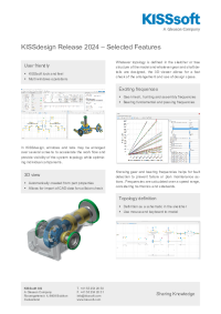
KISSdesign allows intuitive concept design on a system level. In addition to the elementary components, complete gearboxes can now be designed in a separate module. The main focus lies on fast concept building and simple kinematics calculations. This is of benefit particularly in the initial phase of a project, when an engineer needs to be able to roughly model different variants of possible solutions in order to compare critical criteria.
Sketcher
With the sketcher, the user can create their own models by simply drawing them as they would on a piece of paper. This symbolic representation allows them to very quickly define multiple variations of a kinematic concept. The sketch view provides an abstract overview of the complete transmission system, whereby the individual elements of the model can be changed easily. A 3D view of the model is then generated and updated, whenever a change is made in the sketcher.
Shifting Transmissions
Shifting transmissions are also very easy to create with KISSdesign. The user can just drop the elements needed in the tree, draw them in the sketcher or even mix both methods. Once the shifting elements and the gears are connected, and the input power is defined, the user can use the lay out function of the speed table. All possible shifting speeds are then generated, and all shifting elements in the model are automatically set as open or closed for each speed.
System Load Spectrum
A system load spectrum can be created, in which a user-defined number of parameters are varied. Boundary conditions for loads, losses, gear factors, shaft temperatures, and many other values can be defined as varying parameters in the spectrum. Different application cases can then be created with multiple variations of requested service lives. A simple kinematic load spectrum analysis or the entire strength analysis can then be performed. An evaluation of each individual load bin in the load spectrum can also be calculated.
Thermal Rating
The efficiency calculation can be used to estimate the heat level in a particular gear unit. Thermal analysis can therefore be defined in two sections: power loss and heat dissipation. Meshing and churning losses are taken into account for gears, whereas rolling as well as sliding friction are considered for bearings and seal friction for seals. Heat dissipation can be categorized as heat dissipation through the housing, foundation, rotating parts and cooling oil flow. A gear unit's total efficiency and total heat dissipation capacity for a given lubricant temperature, cooler power and input power can be calculated.
Housing Deformation
As gear units become ever more powerful, but ever smaller in size, it is increasingly important that housing stiffness is taken into account in gear unit calculations. This can be achieved by using the reduced stiffness matrix of an FEM model of the housing, with the nodes at the center of support bearings representing the master nodes. Than the bearings are included in the calculation, but without taking clearance into account. The resulting bearing offset has a direct effect on all subsequent calculations.
Characteristic frequencies
Each rolling bearing, gear and shaft has its own characteristic frequencies. Through KISSdesign, a special calculation module enables the collection of the characteristic frequencies of rolling bearings, gears and shafts of a modelled transmission. Several tools for detailed analysis are available, as well as the user input of the frequencies for additional components. With the help of two diagrams in the graphics section, the results window and the special report, the modeled transmission can be optimized to avoid unwanted resonances and reduce the NVH.
Modal Analysis
Modal analysis can be run on an entire gear unit model. A selection of purely torsional vibrations, linked torsional, axial or bending vibrations is possible. The result is displayed in a 3D animation of the vibrating shaft system and also exported in a table. Eigenmode amplitudes are standardized at 1. In every case, the transfer matrix method is used for the calculation. Different models are available for the contact stiffness: ISO 6336, contact analysis, infinite stiffness and zero stiffness.
Campbell Diagram
The calculation of the Campbell diagram is available when dynamic analyses are performed in entire shaft systems. The shaft system's eigenfrequencies are calculated for an operating speed range on one of the shafts. The results are output together with the shaft's excitation frequencies and the toothing as a plot, a report and in a table.
Forced Response
In addition to the unbalanced mass forces, two other types of excitations can be considered. The main source of excitation includes the gear mesh forces resulting from peak-to-peak transmission error and variable non-linear meshing stiffness. Based on the static transmission error of the gears, the transient bearing loads are calculated considering the inertias and masses. It is also possible to include the externally applied torque ripples. The excitations from the torque ripple are added to the effect of the transmission error and the system response is calculated as the result of both excitations.